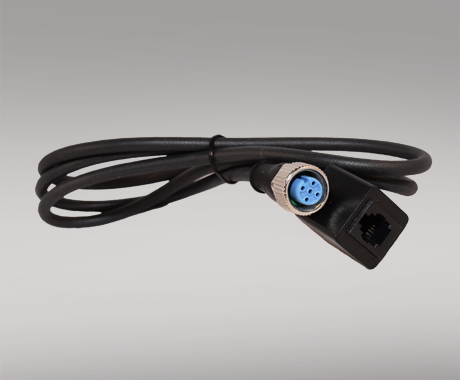
Compact RTD temperature transmitter
PR 5802
- RTD or Ohm input
- Accuracy: Better than 0.1% of selected range
- 2- / 3-wire RTD connection
- Programmable sensor error value
- Output 4...20 mA, with or without M12 connector
Application
- Linearized temperature measurement with Pt100...Pt1000, or Ni100...Ni1000 sensor.
- Conversion of linear resistance variation to a standard analog current signal.
Technical characteristics
- Within a few seconds the user can program PR5802 to measure temperatures within all RTD ranges defined by the norms.
- The RTD and resistance inputs have cable compensation for 3-wire connection.
Mounting / installation
- For tube mounting, e.g. M18 barrel housing or customer specific housing.
- The unit is tested with an M12 connector, mounted in a steel housing and molded with Silgel 612 silicone molding compound. This is PR electronics' recommended method to comply with specifications and EMC data.
Data sheet & Manuals
Data sheet
- 5802.pdf
- Latest version
Manuals
- 5802V102_UK.pdf
- 5802V101_UK.pdf
- 5802V100_UK.pdf
- Previous versions
- Latest version
Supplementary documentation
Download Software
View variants
Environmental Conditions
| Operating temperature | -40°C to +85°C |
| Storage temperature | -40°C to +85°C |
| Relative humidity | < 95% RH (non-cond.) |
Mechanical specifications
| Dimensions, PCB only (WxHxD) | 5.0 x 15.50 x 38.0 mm |
| Dimensions (incl. M12 connector) | 9.5 x 15.50 x 47.70 mm |
| Weight approx. |
2.65 g 5802A1xx
4.05 g 5802A2xx |
Common specifications
Supply |
|
| Supply voltage | 8.0...35 VDC |
| Internal power dissipation | 25 mW…0.8 W |
Response time |
|
| Response time (programmable) | 0.33...60 s |
| Voltage drop | 8.0 VDC |
| Warm-up time | 5 min. |
| Programming | PR 5909 Loop Link communications interface |
| Signal / noise ratio | Min. 60 dB |
| Signal dynamics, input | 19 bit |
| Signal dynamics, output | 16 bit |
| Effect of supply voltage change | < 0.005% of span / VDC |
| Accuracy | Better than 0.1% of sel. range |
| EMC immunity influence | < ±0.5% of span |
Input specifications
RTD input |
|
| RTD type | Pt100, Ni100, lin. R |
| Cable resistance per wire | 10 Ω (max.) |
| Sensor current | > 0.2 mA, < 0.4 mA |
| Effect of sensor cable resistance (3-wire) | < 0.002 Ω / Ω |
| Sensor error detection | Yes |
Common input specifications |
|
| Max. offset | 50% of selected max. value |
Output specifications
Common output specifications |
|
| Updating time | 135 ms |
Current output |
|
| Signal range | 4…20 mA |
| Min. signal range | 16 mA |
| Load (@ current output) | ≤ (Vsupply - 8) / 0.023 [Ω] |
| Load stability | ≤ 0.01% of span / 100 Ω |
| Sensor error indication | Programmable 3.5…23 mA |
| NAMUR NE43 Upscale/Downscale | 23 mA / 3.5 mA |
| of span | = of the presently selected range |
Observed authority requirements
| RoHS | 2011/65/EU |
Do you need help choosing the right device?Our sales engineers are ready to guide you to the device that best fits your application. How to contact us?You can use our quote function or contact form with no obligation. With the quote function, you simply add the devices you are interested in and receive a quote. We will get back to you within 24 hours on business days.
After you orderWhen your order is placed, you will receive a confirmed delivery date within two business days. As soon as your package has been shipped, you will receive an email with tracking details, so you always know where your delivery is. |
 |
State-of-the-art manufacturing Our 8,500 sqm integrated and automated manufacturing campus in Denmark covers the entire value-chain from design and development to manufacturing. It allows us to design and optimize for testing and manufacturing thereby constantly driving quality up and costs down. |
 |
Dedicated Presale / Aftersales
|
 |
Product reliability |
 |
Product deployment
|
 |
Smart products |


