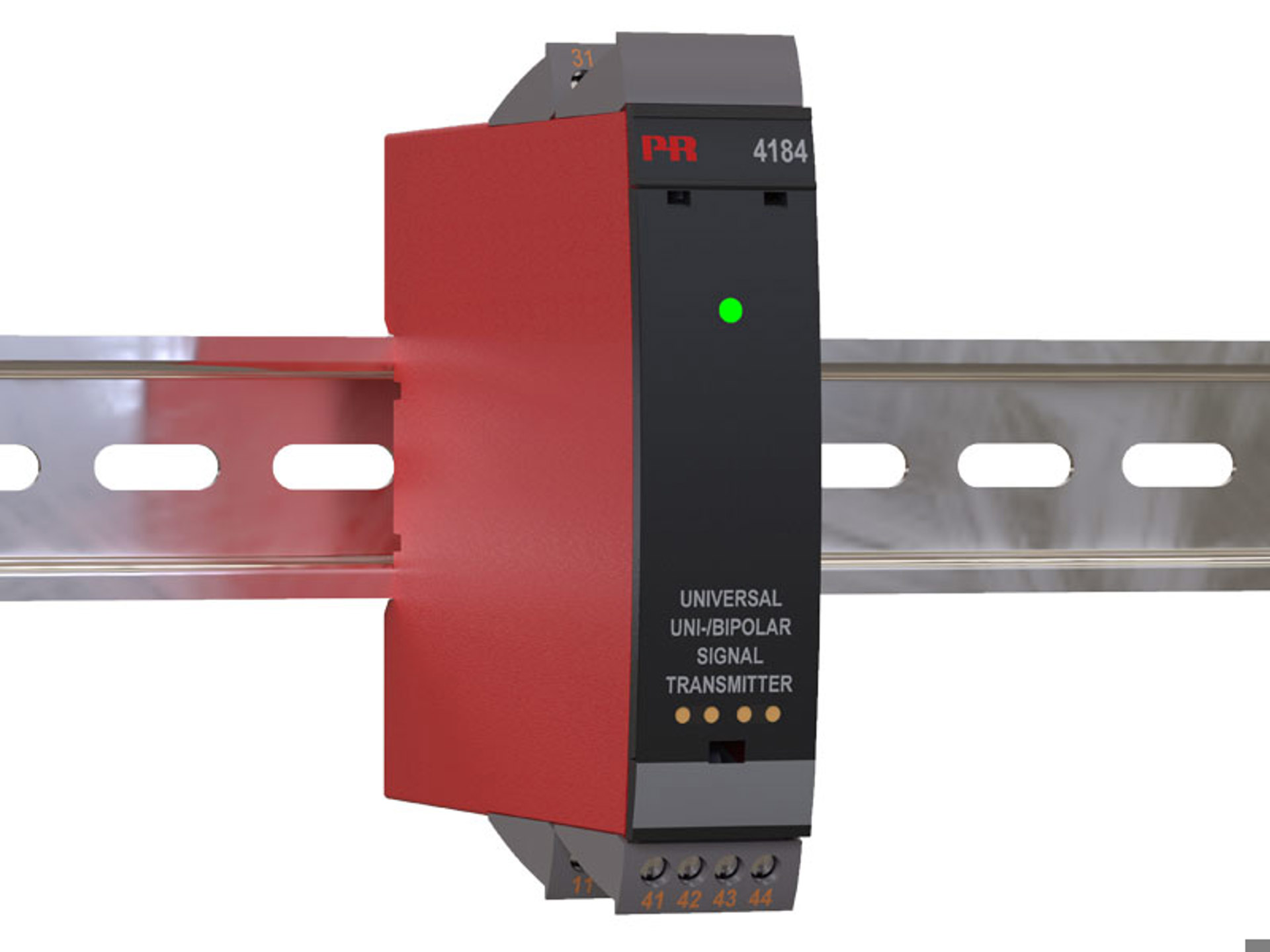
Universal uni-/bipolar signal transmitter
4184
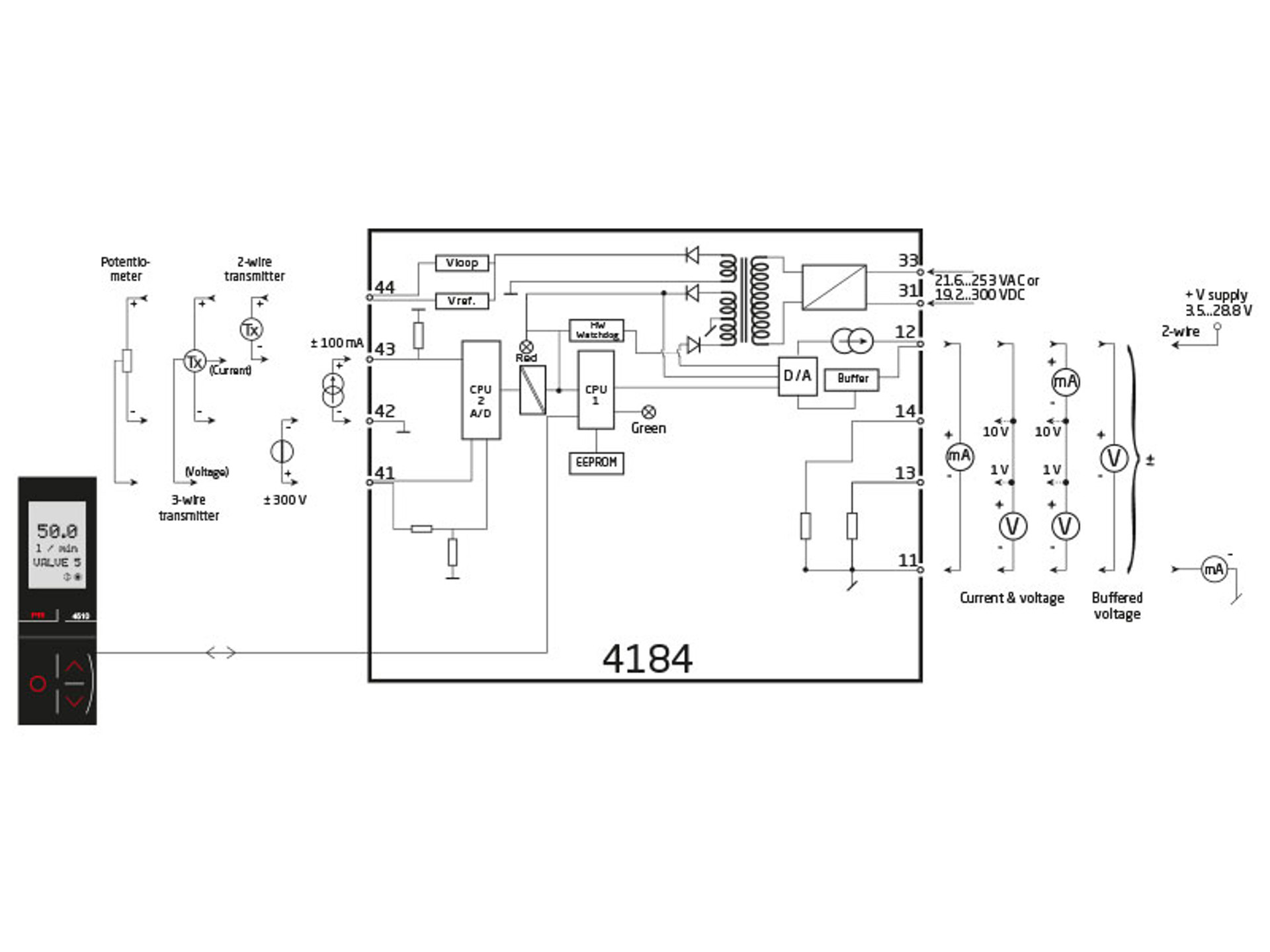
- Measures DC inputs up to ±300 V / ±100 mA with spans as low as 25 mV / 0.5 mA
- Passive/active current output and buffered voltage output
- Fast < 20 ms response time and excellent 0.05% accuracy
- Universally powered by 21.6…253 VAC / 19.2...300 VDC
Application
- Fast < 20 ms response time for measuring signals produced by torque, position, current & acceleration sensors.
- User configurable bipolar or unipolar I/O means the 4184 is suitable for nearly any DC voltage or current conversion.
- Freely programmable between ±300 VDC and ±100 mA.
- The excitation source allows measurement of a 2-wire or 3-wire transmitter, or a potentiometer.
- Converts narrow bipolar inputs to wide bipolar or unipolar outputs, e.g., ±1 volt input = ±10 volt or 4...20 mA output.
- Configurable input limits control the output value for increased safety.
- ±20 VDC buffered voltage output for controlling devices like the PVG 32 valve (6...18 VDC).
- The 4184 provides the required failure data (SFF and PFDAVG) for SIL 2 applications as per IEC 61508 / IEC 61511.
- Failure rates for 4184 correspond to Performance Level “d” according to ISO-13849.
Technical characteristics
- The latest analog and digital techniques are used to obtain maximum accuracy and immunity to interference.
- Possibility of output safety readback by selecting S4...20 mA output.
- The current output can drive up to 1000 Ohms, with an adjustable response time of 0.0…60.0 seconds.
- Exceptional mA output load stability of < 0.001% of span / 100 Ohm.
- Meets the NAMUR NE21 recommendations, ensuring high accuracy in harsh EMC environments.
- Meets the NAMUR NE43 recommendations, allowing the control system to easily detect a sensor error.
- Tested to a high 2.3 kVAC, 3-port galvanic isolation level.
Mounting / installation / programming
- Very low power consumption means units can be mounted side by side without an air gap – even at 60°C ambient temperature.
- Configuration, monitoring, 2-point process calibration and more are accomplished using PR's 4500 series of detachable displays.
Note
- If you need an installation instruction in hard copy, you can order it for free when placing your order.
Data sheet & Manuals
Data sheet
- 4184.pdf
- Latest version
Manuals
- 4184V103_UK.pdf
- 4184V102_UK.pdf
- 4184V101_UK.pdf
- 4184V100_UK.pdf
- Previous versions
- Latest version
Manuals in Russian
- 4184V103_RU.pdf
- 4184V102_RU.pdf
- 4184V101_RU.pdf
- Previous versions
- Latest version
Supplementary documentation
EU Declaration of Conformity
- 4184DoC_EU_101_UK.pdf
- 4184DoC_EU_100_UK.pdf
- Previous versions
- Latest version
UKCA Declaration of Conformity
- 4184DoC_UKCA_100_UK.pdf
- Latest version
SIL declaration
- 4179_4184_SILConformity01.pdf
- Latest version
Modbus configuration manual
- 4184_MCM_100.pdf
- Latest version
FMEDA report
- PR_4184_V1R1.pdf
- Latest version
ISO 13849 declaration
- 4184_ISO_13849_declaration.pdf
- Latest version
EMC data
- 4000_EMC_data.pdf
- Latest version
PR default configurations
- PR_default_configurations.pdf
- Latest version
China RoHS
- China_RoHS.pdf
- Latest version
Safety note
Safety note
- SN4000-1-108-2503.pdf
- SN4000-1-107-2420.pdf
- SN4000-1-106-2109.pdf
- SN4000-105-2001.pdf
- Previous versions
- Latest version
Approvals & Certificates
UL certificate
- 4104_4179_4179B_4184_UL.pdf
- Latest version
EAC declaration
- EAC-Declaration.pdf
- Latest version
Order form
Environmental Conditions
| Operating temperature | -20°C to +60°C |
| Storage temperature | -20°C to +85°C |
| Calibration temperature | 20...28°C |
| Relative humidity | < 95% RH (non-cond.) |
| Protection degree | IP20 |
Mechanical specifications
| Dimensions (HxWxD) | 109 x 23.5 x 104 mm |
| Dimensions (HxWxD) w/ PR 4500 | 109 x 23.5 x 131 mm |
| Weight approx. | 155 g |
| Weight incl. 4501 / 451x (approx.) | 170 g / 185 g |
| DIN rail type | DIN EN 60715/35 mm |
| Wire size | 0.13...2.08 mm2 AWG 26...14 stranded wire |
| Screw terminal torque | 0.5 Nm |
Common specifications
Supply |
|
| Supply voltage, universal | 21.6...253 VAC, 50...60 Hz or 19.2...300 VDC |
| Max. required power | ≤ 2.5 W |
| Internal power dissipation | ≤ 2.0 W |
Isolation voltage |
|
| Test voltage | 2.3 kVAC |
| Working voltage | 250 VAC (reinforced) / 500 VAC (basic) |
Response time |
|
| Response time (0...90%, 100...10%) | < 20 ms |
Auxiliary supplies |
|
| 2-wire loop supply | > 16 V @ 23 mA |
| 3-wire loop supply | > 18...< 28 V @ 23...0 mA |
| Loop supply limitation | 27...35 mA avg., < 80 mA peak |
| Reference voltage | 2.5 VDC ±0.5% |
| Reference voltage, load | 0...15 mA |
| Current limit, reference voltage | < 60 mA |
| Programming | PR 4500 communication interfaces |
| Signal dynamics, input | 24 bit |
| Signal dynamics, output | 18 bit |
| Signal / noise ratio | > 60 dB |
| Bandwidth | > 40 Hz |
| Accuracy | Better than 0.05% of selected range |
| EMC immunity influence | < ±0.5% of span |
| Extended EMC immunity: NAMUR NE21, A criterion, burst | < ±1% of span |
| Conducted emission, cl. A | 150 kHz...10 MHz |
Input specifications
Current input |
|
| Signal range | ±100 mA |
| Programmable measurement ranges | 0...1, 0...5, 1...5, 0...20, 4...20, ±1, ±5, ±10, ±20, ±50, ±100 mA |
| Custom configurable signal range | ±100 mA |
| Min. measurement range (span) | 0.5 mA |
| Input voltage drop | 0.6 V @ 20 mA nom. |
Voltage input |
|
| Signal range | ±300 VDC |
| Programmable measurement ranges | 0...0.1, 0...1, 0.2...1, 0...2.5, 0...5, 1...5, 0...10, 2...10, 0...100, 0...300, ±0.1, ±1, ±2.5, ±5, ±10, ±100, ±300 V |
| Custom configurable signal range | ±300 V |
| Min. measurement range (span) | 25 mV |
| Input resistance |
Nom. 3 MΩ (> 2.5 VDC)
Nom. > 10 MΩ (≤ 2.5 VDC) |
Potentiometer input |
|
| 3-wire potentiometer input | 0...100% |
| Reference voltage | 2.5 V |
| Calibration resistance | 5 kΩ |
| Min. potentiometer resistance | 200 Ω |
Output specifications
Current output |
|
| Signal range |
0...23 mA (unipolar)
-23...+23 mA (bipolar) |
| Custom config. output range | ±20 mA |
| Min. signal range | 4 mA |
| Load (@ current output) | ≤ 1000 Ω / ± 20 V @ ±20 mA |
| Current limit |
≤ 28 mA (unipolar)
± 28 mA (bipolar) |
| Load stability | ≤ 0.001% of span / 100 Ω |
| Response time, programmable | 0.0...60.0 s |
Passive 2-wire mA output |
|
| Programmable ranges | 0...20 and 4...20 mA |
| Ext. 2-wire loop supply range | 3.5...28.8 VDC |
Voltage output |
|
| Programmable signal ranges |
0/0.2...1; 0/1...5 ; 0/2...10 V
±1, ±5 and ±10 V Direct or Inverted action |
| Load (@ voltage output) | ≥ 500 kΩ |
| Response time, programmable | 0.0...60.0 s |
Shunted voltage output |
|
| Signal range | ± 1.2 V / ± 12 V |
| Programmable standard ranges | 0...1, 0...2.5, 0...5, 1...5, 0...10, 2...10 V ±1, ±2.5, ±5, ±10 V |
| Min. span | 0.8 V |
| Custom config. output range | ±10 V |
| Load, min. | > 500 kΩ |
Buffered voltage output |
|
| Signal range | ± 23 V |
| Programmable standard ranges | 0...1, 0.2...1, 0...2.5, 0...5, 1...5, 0...10, 2...10, 0...20, 4...20; ±1, ±2.5, ±5, ±10, ±20 V |
| Min. span | 0.8 V |
| Custom config. output range | ±20 V |
| Current limit | < 50 mA |
| Load, min. | > 2 kΩ |
Observed authority requirements
| EMC | 2014/30/EU & UK SI 2016/1091 |
| LVD | 2014/35/EU & UK SI 2016/1101 |
| RoHS | 2011/65/EU & UK SI 2012/3032 |
| EAC | TR-CU 020/2011 |
Approvals
| c UL us, UL 508 | E248256 |
| SIL | Hardware assessed for use in SIL applications |
Need support to select the right product for your application?
Our sales engineers are ready to help specify the right device to meet your needs.
Reach out by phone to get in touch with us straight away – or use the contact form or quick quote function to send your RFQ directly from the website. You’ll get a response within 24 hours on normal business days.
You can expect to get a confirmed delivery date via email within 2 days after we have received your order.
As soon as your package leaves our warehouse, you’ll receive tracking details via email. And if you have any questions along the way we’re just a phone call or email away.
 |
State-of-the-art manufacturing Our 8,500 sqm integrated and automated manufacturing campus in Denmark covers the entire value-chain from design and development to manufacturing. It allows us to design and optimize for testing and manufacturing thereby constantly driving quality up and costs down. |
 |
Dedicated Presale / Aftersales
|
 |
Product reliability |
 |
Product deployment
|
 |
Smart products
Check out our range of communication interfaces
|


